Ring profiles and precision working surfaces
EHWA presents tools for processing silicon and silicon carbide components. The documents connect coring a plate with machining ring profiles and fine grinding selected surfaces. Focus rings provide a specific component example.
Material and processing stage remain explicitly assigned. The source lists electroplated rough grinding tools for Si focus rings and vitrified or resin-bonded fine grinding tools for Si and SiC focus rings. Both materials are listed together only where that relationship is actually described.
Match the tool shape to the task
| Source application | Material relationship | Tool design |
|---|---|---|
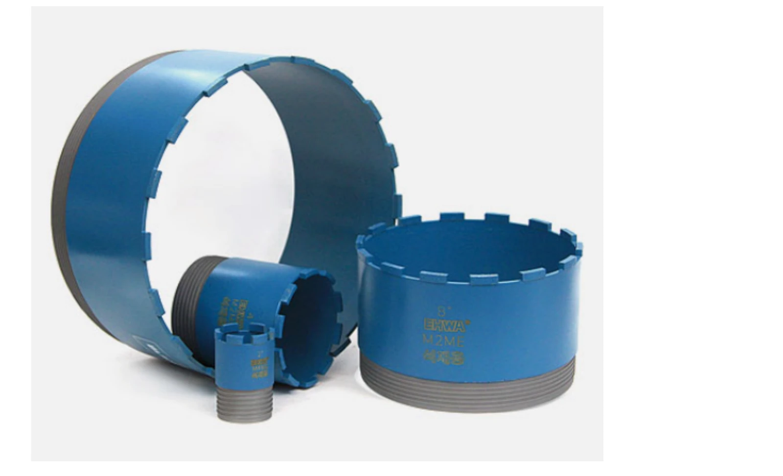
| Coring a plate to create a ring-shaped structure | Si or SiC | Core wheel with electroplated, sintered or brazed tips |
| Rough grinding outer/inner profiles, tapers and other forms | Si focus ring | Electroplated grinding tools |
| Fine grinding selected profiles and surfaces | Si or SiC focus ring | Vitrified or resin bond |
| Wafer edge or notch processing | Si/SiC wafers in the source section | Profiled edge and notch tools |
Consider profile, bond and finish together
For coring, EHWA describes different tool shapes and abrasive-layer designs. Selection connects useful life, grinding ability and dimensional accuracy. The profile grinding documents show tools for chamfering, hole grinding and internal profile processing.
Fine grinding is treated as a distinct stage. The source illustrates different tool arrangements for Si and SiC rings. This highlights the need to consider component geometry, working surface and machine together. Tool design is matched to the required profile and surface finish.
For wafer edges, EHWA describes configurable groove profiles, consistent chamfer width and strong profile retention. Multi-stage tool designs can combine rough and fine processing. The associated notch tools work on a different geometry from the continuous wafer edge, so their design follows the specific notch task.
Source example: Fine grinding a SiC focus ring
The single-page EHWA document shows a SiC focus ring on a rotary surface grinding machine. The workpiece is identified as sintered SiC or CVD-SiC. The illustrated process uses emulsion and lists a wheel speed of 50–70 m/s.
Source: Si/SiC Parts Grinding Wheel, PDF page 1, visually checked. These details belong to the illustrated grinding example. The actual wheel, its marking, the SiC material and machine configuration determine applicability to another process.
The ring cross-sections also identify the surface being ground. This is more useful for tool design than a general request to grind SiC. Outer profiles, inner profiles and plane surfaces can require different tools and processing stages.
Discuss your Si/SiC component
Provide the material type, drawing, working surface, stock and machine. For an existing process, tool dimensions, specification, coolant and required finish support the discussion. For wafer edges, add the chamfer or notch geometry and existing process sequence. The available information provides the starting point for a tool design linked to the actual component.
EHWA Europe: info@ehwadia.de · +49 6173 997780
Sources and original documents
- EHWA: Si/SiC Parts Grinding Wheel and Wafer Edge/Notch Wheel · PDF pages 1–4.
- EHWA: Si/SiC Parts Grinding Wheel, overview · PDF page 1, including the SiC focus-ring example.